Things I wish I knew in Motion Capture: L-Frame placement relative to force platforms
- Katie Bradley

- Dec 1, 2021
- 4 min read
I don’t remember much about my first day in the motion capture lab, but I remember how much accurate placement of the L-Frame was stressed. It was said over and over and over again. It’s a research lab, accuracy is important, got it… but why? What happens if I don’t place the L-Frame accurately? And what is “accurate”?
First, some background – with an optical motion capture system several cameras are placed around a room pointing at a common location (image below). The area where the camera’s field of view (pink) overlaps defines the capture volume (purple). The L-Frame (black) defines the lab axes (Red, Green, Blue) and is usually set on or near the force platforms (blue):
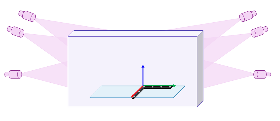
The position and orientation of the cameras is determined by calibrating the volume – typically this is done by moving a calibration wand through the capture volume. The wand has markers with known positions and as each camera measures the wand moving through the volume, it’s possible to determine the location of the cameras relative to one another. After the cameras are calibrated, an L-Frame (or wand) is placed on the ground to set the origin of the capture volume. The origin determines the (0,0,0) location and the orientation of the lab (typically by defining the plane along ground). Motion capture systems are very accurate and are able to track a marker moving through space with submillimeter accuracy. In biomechanics research, motion capture systems are often used to track a person walking by placing surface markers on the subject. The markers are used to estimate the position and orientation of the person’s bones, but due to soft tissue artifact (the skin moving relative to the bones), the accuracy of estimating the position of the bones is not submillimeter from surface markers, but that’s a story for another day.
In addition to measuring the location of markers, motion capture systems often have force platforms integrated into the system. Force platforms allow you to measure the force exerted on the ground – so how much force is applied to a person’s foot during gait or a jumping task. When collecting force platform data, it’s important to determine the location of the force platform in the motion capture volume. This allows you to analyze the marker data and force data simultaneously. In a motion capture system, the force platform corners are defined in relation to the L-Frame (or wand or whatever you use to define the origin of the lab). These corners are fixed in the L-Frame coordinate system (CS), so even though the force platforms are bolted to the ground, if the L-Frame is moved, the corners in the software will move relative to their actual location. In order to calculate inverse dynamics, the marker data and force platform data must both be in the same CS, so the force platform corners are used to transform the data from the force platform CS to the motion capture CS (the marker data is in the motion capture CS). So in short, to calculate kinetics we need the force and motion capture data in one CS and to do this, we use the force platform corners to transform data from the force platform local CS into the motion capture CS.
If the force platform corners are defined aligned with the lab platform CS, and I place the L-Frame rotated 20 degrees, the corner locations in the motion capture CS will translate relative to their actual location. It’s important to note that when the L-Frame is rotated, the furthest force platform will translate the most:

Now, rotating the L-Frame 20 degrees would be a big mistake, and one I should notice – but what about 1 degree? I could easily place the L-Frame rotated 1 degree by accident. Let’s say there are three force platforms in a straight line and each are 0.4 m x 0.6 m; the furthest corner would be (0.4, 1.8, 0) meters away from the origin. What would be the difference in C (the actual corner location) and C’ (the corner location in the motion capture system)?
We know the equation to transform a point from one coordinate system to another (1), and we only rotated 1 degree about the Z axis, so we know this rotation (2):

Since the origin hasn’t translated O is zero, and we know C’ (the specified location of the corner):
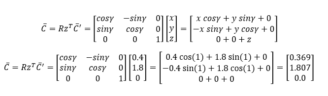
This means if the L-Frame is rotated 1 degree, this corner translates 0.03 meters along the X axis and 0.01 meters along the Y axis. A 0.03-meter shift doesn’t seem like a huge difference, but how would this affect a joint moment?
If we pretend this is a simple statics problem, and we calculate the torque (or moment) about the Y axis, and the center of pressure (COP) just shifted 0.03 meters along the X axis relative to the segment coordinate system, the torque could increase from 0 Nm to 29 Nm:

Now, this is a gross oversimplification of the problem and the COP wouldn’t be at the corner of the force platform – but the takeaway is that the placement of the L-Frame affects the COP location. A small rotation of the L-Frame could (or could not) have a noticeable effect on your joint moments – and the distance between the L-Frame and the force platform can influence this.
Chances are there is a gap between the flooring and your force platforms (so the flooring doesn’t rub on the force platform and appear as external forces) so everyone in the lab must ensure the L-Frame is placed consistently (flush against the flooring, flush against the force platform, etc.).
If you have a treadmill and overground plates, should you place the L-Frame in the same location for both data collections? Since the greater the distance between the L-Frame and the force platforms, the greater the effect of any rotation of the L-Frame, so the L-Frame should probably be set closer to the treadmill when collecting treadmill data. This could mean it’s worth having two lab setups in the motion capture system, one where the L-Frame is placed near the treadmill and another near the overground force platforms. Keep in mind that some analysis software requires gravity to be along a principal axis of the lab, which means you can’t incline the treadmill and then set the origin on the inclined treadmill. In this case, you may want to create a jig (place targets fixed on the treadmill) to update the force platform corners relative to the jig.


Comments